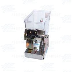
This is the log from a project from 2009, the idea was to build an arcade machine that pays the player if they clock the game. I achieved it with a modified version of MAME, a shitload of dodgey hardware hacking and a couple of near death experiences with 240V electricity.

Raiden has a new home

2010-09-21 08:36:45

Raiden has moved to Game Traders in Carillon City Arcade, go there, play it, win $

2010-09-01 02:42:03

DONE!

2010-04-10 12:03:14

It's finally done! It's all working marquee inside, better speakers, paying out properly. This is a good feeling!

Coming soon: Properly writen instructions to build your own. (and photos/video of the final product!)

hooray!

2010-04-10 04:17:55

my enthusiasm has returned! i made a badass marquee, got it printed at office works only to realise just around the time that office works shuts that they scaled it, when i said it can't be scaled, but i'm not letting it frustrate me, i said the f and c words a few times now im fine! heres a picture of the marquee

fuck

2010-03-21 05:17:36

fuck i hate this fucking project

Windows XP Auto-login

2010-02-24 03:18:31

The tweakui autologin wasn't working properly, it would autologin once, but after that i'd be prompted for the password again, so I'm making the change in the registry, the method is outlined here but since microsoft are always changing the way their website is laid out ill paste it in below:

You can use Registry Editor to add your log on information. To do this, follow these steps:

  1. Click Start, click Run, type regedit, and then click OK.

  2. Locate the following registry key:
    HKEY_LOCAL_MACHINE\SOFTWARE\Microsoft\Windows NT\CurrentVersion\Winlogon

  3. Using your account name and password, double-click the DefaultUserName entry, type your user name, and then click OK.

  4. Double-click the DefaultPassword entry, type your password under the value data box, and then click OK.

    If there is no DefaultPassword value, create the value. To do this, follow these steps:

    1. In Registry Editor, click Edit, click New, and then click String Value.

    2. Type DefaultPassword as the value name, and then press ENTER.

    3. Double-click the newly created key, and then type your password in the Value Data box.


    If no DefaultPassword string is specified, Windows XP automatically changes the value of the AutoAdminLogon registry key from 1 (true) to 0 (false) to turn off the AutoAdminLogon feature.

  5. Double-click the AutoAdminLogon entry, type 1 in the Value Data box, and then click OK.

    If there is no AutoAdminLogon entry, create the entry. To do this, follow these steps:

    1. In Registry Editor, click Edit, click New, and then click String Value.

    2. Type AutoAdminLogon as the value name, and then press ENTER.

    3. Double-click the newly created key, and then type 1 in the Value Data box.


  6. Quit Registry Editor.

  7. Click Start, click Restart, and then click OK.


After your computer restarts and Windows XP starts, you can log on automatically.

Coming up: BIOS Hacking!! Do I dare?

Making the monitor switch on when you power the machine

2010-01-23 04:37:04

I needed to have the monitor switch on as soon as power is fed to the machine, before this mod I'd have to press the button to switch on the monitor after switching on the power, not very practical.

I don't know if the monitor stores charge like a CRT does, doing this may be dangerous!


It's a Benq FP91G+


Unscrew the screws, all of them are uncovered except two which are covered by some rubber stuff that just comes off. The circled bit is the circuit board with the buttons, the power button is on the right side of the board.


Theres all the buttons!


That's the button


Those top two solder joint connect the on switch, so I'm just gunna solder them together to bypass the switch.


Connect them up, put it back together and it works sweet!

2010-01-22 05:43:30

Got some spare time so I'm gunna put in some work. The activation on the machine i was using fucked up the whole thing and i couldn't activate or start the computer, so i got all the files off it and am reinstalling windows, this means i have to go through all that crap of suppressing windows, good thing i wrote it all down here!

Things left to do:

  • Hook up the light in the marquee part

  • Design and get marquee printed

  • Get a little hood for where the cash comes out

  • Fix pc in place inside the machine

  • Sound, get amplifier

  • Figure out what to do with the monitor

beta

2009-10-12 02:37:32

[flv:uploads/dl/beta.flv 640 480]

discharging your monitor, australian lowboy

2009-10-07 07:54:32

Uh oh! AC! For this little task I called in my more "big electrical" minded brother since i was too pussy to do it myself. The basic idea is to hook up a cord to an insulated screw driver, hook the cord to the metal frame of the machine, stick the screw driver up in to the anode and discharge all that pent up teen angst from the capacitors inside the monitor. Apparently you should hear anything from a little crackle to a loud noise & blue flash, we heard a little crackle which was nice.

All the videos and tutorials on the internet seem to be for American models which have a big metal frame around the monitor which you ground the screwdriver cord to, the low boys don't seem to do it this way so we hooked it up to some metal part near the main video pcb, see pictures below.


Be careful and make sure you read up a LOT of information before you do this so you don't kill yourself!

baggage x ?

2009-10-05 01:38:04

Got the schematic and pcb layout all done (hopefully it's all wired right), tried to make the pcb twice, FAILED miserably both times, the transfer didn't stick to the board properly, so I'm going to try a new method instead of the clothes iron which is feeding the board and film through a laminator a bunch of times, all i have to say is fucking BAGAGGAGWGHAGAWEEGWAEEGWAEGH@#$)^!*$_&(3479

Edit: The laminator also failed

gEDA Rundown

2009-10-04 09:33:07

This tutorial is perfect to get you started, run it through and you'll have a clear idea of how gEDA works. gEDA Intro Tutorial

To design a pcb in geda you:

  • Design the schematic in gschem

  • Convert to pcb with gsch2pcb

  • Move parts around in pcb

  • Output image from pcb


gschem Keyboard Shortcuts:

  • Undo: u

  • Edit Component: ee

  • Rotate Component: er

  • Mirror Component: ei


pcb Keyboard Shortcuts:

  • Select all routes of component the mouse is over: f


Auto numbering components resdef values: refdes_renum raiden.sch

Creating PCB with extra footprint files: gsch2pcb --use-files --elements-dir ~/footprints SCHEMATIC_NAME
2009-10-04 00:52:50

Trying to design the PCB for the control board today, I've got the full etching kit, I found it very hard to find good software, I've ended up using gEDA, it's good but very complicated. It's such an engineers program, all the keyboard shortcuts are different than usual and it uses the middle mouse button for stuff!!

I can only get it running on linux so I've got VMWare player along with a prepacked version of Fedora for VMWare.

Will post back the results once it's done

actually

2009-09-29 09:00:37

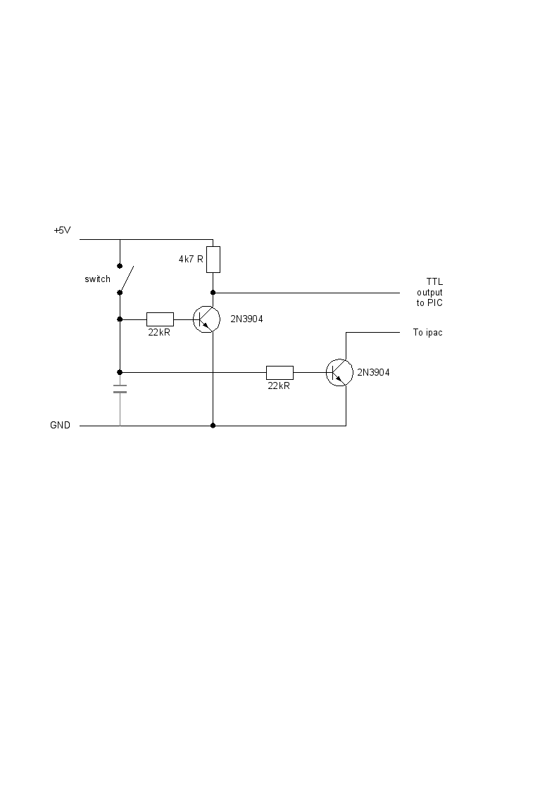
That last picture was wrong coz the ipac is 5v normally, the pic is the opposite, here the proper (working!) layout:

2009-09-29 06:52:24

Currently trying to hook up the control panel to interact with the ipac, the electronics is boggling me so I went on to IRC to get help, which I don't usually like doing coz I always feel like such a noob, but I went on #electronics on freenode and they were very helpful. One guy even drew me a little schematic of what I've got to do!!

strange booting requirements

2009-09-27 15:25:45

So I've set up my control board to be powered by the computer, which was pretty easy, red wires from the PSU are +5 and black are gnd. But during this little change I came across another glitch... The run.bat needs a pause before it runs otherwise the programs it's running stops after about half a second. So my run.bat now looks like this (ie you'll get a blank screen when you switch on the game until you press a button)
pause
c:\init.exe
c:\mame\mame.exe -rompath c:\mame\roms -ror raiden

autologon mouse pointer

2009-09-27 10:06:20

NOTE: Just figured out (after lots of frustration) that you have to use one of the System mouse pointer schemes and move the .cur file to c:\windows\cursors\ otherwise there will be a slight second that the original mouse pointer shows up just before mame loads.

suppressing shell window

2009-09-27 09:14:26

When windows loads we go straight into run.bat instead of explorer, unfortunately we see a quick flash of that shell screen before mame loads, this is how I suppressed it.

  1. Put a "pause" at the start of run.bat

  2. Restart

  3. Click the icon (top right), then properties

  4. Under the "layout" tab in "window position" move the window off the screen


Simple!

Suppessing mame warnings

2009-09-27 06:18:08

So the function that shows those warnings is in the src/emu/ui.c file, ui_display_startup_screens

This function is called in src/emu/mame.c but we can't just comment out that line because it stuffs some other stuff up.

So, open up src/emu/ui.c

Around line 260 of that file set
int show_warnings = FALSE;
int show_gameinfo = FALSE;
show_disclaimer = FALSE;

Recompile and you're good to go!

2009-09-27 03:29:13

I've decided just to use a generic bootskin since I can't seem to figure out how to make my own. The one I'm using is called AbstractBoot and it looks like this:


Should look fine sideways, heres a local copy

I've been pondering whether to try modify the bios so I don't get all that crap when I switch on the computer... I'll have a brief google for it but it's low priority.

today

2009-09-27 01:18:10

Found some time to do some work on the machine, so I'm going to work on suppressing windows, fix mame so I don't get that "NOTE: YOU MUST OWN THIS GAME BLAH BLAH BLAH". Also going to try to figure out exactly what I need for the cabinet as far as wood, perspex etc. And also try get that end sequence program going.

2009-09-20 10:20:04


Here's my machine! I've really gotta remember to bring my camera back in to the studio.

I've decided I'm going to work on Double Dragon before I work on mine so I don't finish mine then never get around to fixing Sarans machine. It seems pretty hard to find technical info on arcade machines so I'm going to commit and buy this: "Randy Fromm's Big Blue Book of Great Technical Information". It's pretty expensive for ebooks but in retrospect I didn't pay anything for my machine, and this looks like it's got some really good info.

ohhhhh shiiiittttt!

2009-09-14 04:50:12

Got a cabinet! My main geezer Saran is hooking me up in exchange for fixing up a couple of others, original Simpsons & Double Dragon, which I'm frothing on getting a go at rooting around inside of. Looks like this project could finally be coming to completion.

Winner picture

2009-09-07 09:26:53

Today

2009-09-07 03:13:10

Going to work on some allegro stuff for the "winner" screen today, can't just have the program just go blank when you win, I also need to change the call from mame to open the program to the full location of the payout program, ie C:\mame\prog.exe

parallel port initialization

2009-09-06 12:10:28

OK fixed that problem, the PIC doesn't do anything now until it sees the parallel port switch on SW4 (payout switch) for like half a second, so I've got a program called init.exe which is run before mame is started, that way there is no funny biz.

Next thing i need to know is what on the parallel port do i really need to have plugged in, I'll probably just try work that out with trial and error, bit worried because I remember reading "make sure you have all your parallel port wires connected correctly or you could damage your motherboard", hopefully thats just talking about inputs.

NOTE TO SELF: The files I'm working with are:

  • C:\payout prog\init.exe (C:\payout prog\on_off_tests.c) COMPILED WITH: gcc on_off_tests.c inpout32.c -o init.exe

  • C:\VELLEMAN\K8048\Examples\raiden_board.asm

Found the newest code

2009-09-06 09:40:04

Wrote this file "raiden_board.asm" to the pic, seems this is the most recent, worked fine, I'm uploading a copy just in case I forget about this project for ages and need to come back to this working point.

raiden_board.asm

Now to start making the init loop

New problem

2009-09-06 09:18:30

The damn parallel port pins go up when the computer initializes, it must be some initialization sequence or something, so I have to reprogram the pic to not do anything when powered on before it receives an init sequence, I'm just going to use a couple of the free pins on the pic rather than implementing the real startup sequence because figuring that out I think will be quite:


The only problem now (well, the most prevalent one) is that I've got to find the most recent version of my PIC code to make that change, and in my usual haphazardous style nothing is named properly and I don't know where it is, thank god I've been keeping this blog otherwise so many times I would have been lost at what I have done and where I was up to.

2009-09-06 09:04:37

Not exactly sure how my layout worked last time but it stopped working once I'd restarted the computer. After a lot of head scratching I think I might have figured it out, the 0v's on both boards need to be connected, this was the main problem, I'm not really sure if every wire in the parallel port has to be hooked up to something but that's how I have it now and it's working so thats what I'm going to go with!

I don't have my camera with me so I'm going to have to take a photo of the setup with my shitty webcam:


So the signal payout wire isn't going to the right place, thats just for testing, it should really be going to the signal payout pin which is the second from top on the left side (with that little dent thing of the chip at the top).

NOTES TO SELF:

  • Grounds must be connected

  • Parallel port doesn't need weird button setup like buttons on the main board

  • Still not sure if every parallel port pin has to be connected up like in the picture


I thought I just posted a thread on the mameworld forums but it seems I got sidetracked and closed the window before I pressed OK coz it's not there, now do I go back on there and type it up again possibly double posting and looking like a goose or do i wait and see if it just takes time to show up and probably forget that's what I was doing?

Anyway this week looks not too busy so I think I'll be able to put in a bit of time and try to finally finish this project!

Suppressing Windows

2009-06-23 14:10:03

The target machine has xp pro, the following is how to go about suppressing xp so it boots straight into the game. My instructions come from here by the way.

  1. BootSkinXp: change the windows logo on boot up, (local copy) (yet to figure out how to make a custom skin)

  2. Suppress Sounds:

    1. Control Panel

    2. Sound

    3. Choose "No Sound" scheme


  3. Disable startup/shutdown screens:


      1. Control Panel

      2. User Accounts

      3. Change the way a user logs on or off

      4. Uncheck "Use Welcome Screen"


      1. Regedit.exe

      2. HKEY_LOCAL_MACHINE> Software> Microsoft> Windows> CurrentVersion> Policies> System

      3. Set DisableStatusMessages string to 1


  4. Login screen background color: Set HKEY_USERS>.DEFAULT>Control Panel>Colors>Background to 0 0 0

  5. Load mame instead of explorer.exe:

    1. HKEY_CURRENT_USER \Software\Microsoft\Windows NT\CurrentVersion\Winlogon

    2. Set Shell to the location of mame.. eg

    3. c:\mame\mame.exe -rompath c:\mame\roms raiden

    4. Add the rompath option because mame won't be executed from the mame directory and will look for the rom in the wrong place.


  6. Download TweakUIXP

  7. Cursors: Make a dark 1px cursor with Greenfish Icon Editor Pro

    1. Save cursors theme in Control Panel/Mouse/Pointers with the dark 1px cursors

    2. In TweakUI go to Logon/Settings and select all the checkboxes and click copy now


  8. Auto login:


    1. TweakUI

    2. Logon

    3. Autologon

    4. Check "Log on automatically at system startup"


2009-06-23 11:40:29

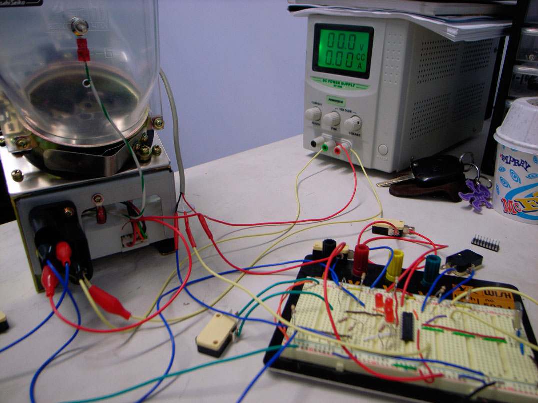
Hooked it up to the computer via parallel port and it works, the game finishes and pays out, heres the picture of the circuit board with the parallel cord hooked up:

Wish board re-built

2009-06-23 08:48:43

Just got the wish board version working, heres an update of my circuit diagram as the last one had a few inconsistencies.


And heres a photo of it:


Now I'm gunna try hook it up to the computer with the parallel port and make it pay out at the end of game.

Time to rebuild test board

2009-06-23 03:27:40

Hope my circuit diagram was correct!

Oh yeah, look at the tool i bought so i stop breaking the pins on my pic's when i take them on and off the wish board...

2009-06-21 11:50:33

Some more good progress, no hiccups for a change.

I'm thinking I'll just write the parallel alert program seperate to mame and have mame execute that program.

I got mame executing an external program when you beat it, just edited nec.c and added this line:

execl("prog.exe","prog.exe",NULL);

into this function:

static CPU_EXECUTE( necv )

inside this if statement:

if (((nec_state->sregs[PS]<<4) + nec_state->ip) == 0xF1E67)

Actually heres the whole function:

static CPU_EXECUTE( necv )
{
nec_state_t *nec_state = device->token;
int prev_ICount;

nec_state->icount=cycles;

while(nec_state->icount>0) {
/* Dispatch IRQ */
if (nec_state->pending_irq && nec_state->no_interrupt==0)
{
if (nec_state->pending_irq & NMI_IRQ)
external_int(nec_state);
else if (nec_state->IF)
external_int(nec_state);
}

/* No interrupt allowed between last instruction and this one */
if (nec_state->no_interrupt)
nec_state->no_interrupt--;

debugger_instruction_hook(device, (nec_state->sregs[PS]<<4) + nec_state->ip);
if (((nec_state->sregs[PS]<<4) + nec_state->ip) == 0xF1E67)
{
// Put code here to handle hopper
mame_printf_info("Hey brow!\n");

// Execute some program
execl("prog.exe","prog.exe",NULL);
}
prev_ICount = nec_state->icount;
nec_instruction[fetchop(nec_state)](nec_state);
do_prefetch(nec_state, prev_ICount);
}
return cycles - nec_state->icount;
}

Unfortunately mame closes when i execute that prog.exe, I'm pretty sure I'm meant to call something else instead of execl, probably time to do some boning up on c. But anyway it's fine if the program just closes and restarts mame while machine pays out, i could even make some little special, "you've won!" thing inside prog.exe

Parallel Port Progress!

2009-06-21 10:51:39

I got the parallel port to work with some help from this page in particular, this file (local). Inpout32.dll is a nice little library that makes the communication with the parallel port a bit easier. Once you write to the port with library the data stays on the register, its not a per cycle thing (i think...) so when mame starts I'm going to have to have inpout32.dll loaded and initialized and set the registers for the parallel port to 0.

The test program made my little led come on! Very exciting!


Heres the computer end of the parallel port:


And heres the end of the cord I'm using:


I hooked up pin 2 to a 1k resistor to a led to pin 19 (to complete the circuit). It's a simpler version of the setup on this page: A tutorial on parallel port interfacing

So the next step from here is to insert my code into mame to bring up pin 2 when you beat the game, this is the same as sending the signal to the pic on the control board that it's time to pay out.

Heres the package for the inpout32.dll package, btw I'm doing all this on XP, not sure if it will work on Vista:

Logix inpout32 Package

Time Enough

2009-06-21 06:03:17

Finally got some free time, although its 8pm on sunday and it's only a few hours, time to commit some parallel port stuff. On the to do list right now:

  • Parallel port communication.

  • Rebuild working model on breadboard.


And then...

  • Find or build cabinet.

  • Finish this mofo!


Thinking of using USB for communication to the pic if parallel turns out to be too bagage, but that would most likely require rewriting the pic software for a usb enabled pic.......

2009-03-29 01:37:54

No progress with pretty much anything at the moment, been hell busy working for the man (me ha!). But I did find this place in the quokka In 2 Amusements which is some Perth amusements place. And they have plans for my all time favorite cabinet, the classic Australian Lowboy, heres a link straight to the pdf, I'm beggining to think that building the cabinet is going to end up being easier than trying to find one. Still, if anyone in Perth reads this and they happen to have a cabinet they want to get rid of holler at me.

2009-03-11 10:57:53

FUCK!


I just finished moving everything from the plug in bread board to a soldered bread board. Yet again I'm working on it late at night after the electronics shop has closed and taken the "not so clever" route. I soldered the PIC straight onto the PCB rather than waiting and getting a plug in thingo, and now it just doesn't work. Also I fed power to the thing the wrong way around for a little bit (10 seconds?), not sure what that does to any of the components though. I don't know why it doesn't work but I'm thinking these are the probable possibilities:

  • Shitty soldering. Solution: Check every stupid little tiny soldering joint.

  • I didn't move the bits from the original board to the same places. Solution: Double check the PCB against the circuit diagram I drew, but then I'm not 100% I drew it correctly, maybe try to compare it to the photo I took of the thing.

  • The soldering iron heated up the PIC too much and broked it. Solution: Unsolder (fuckingfuckgniag) the PIC, install a plug in PIC housing, get a new PIC16F84A, set up the other computer with XP on it because my PIC programmer won't work under Vista, flash the new PIC, plug it into the housing on the PCB.

  • The soldering broke some other component, they seemed to get pretty hot... and no one's told me what the deal is with that. Solution: Try new components.

  • More than one of the above. Solution: Consider a simple honest life with the Amish people.


Heres a picture of the stupid thing just before it was finished:


Frickn balls

Control Board Finished

2009-02-18 03:21:46

We just moved into a new office and since I didn't have any real work to do I've been committing the control board that communicates with the coin hopper. Ironically I haven't had the internet this whole time I've been working on it which makes it extremely frustrating trying to figure stuff out and now that I've got it working the internet has come back on!

I read the first couple of chapters of this book...

... which was extremely helpful for understanding how PIC's work and how they need to be hooked up to a circuit board. Also the data sheet for the PIC16F84A (the chip i used) is pretty gnarly looking at first but after reading it like 50 times it proves pretty useful.

Heres a picture of the control board in its current state:


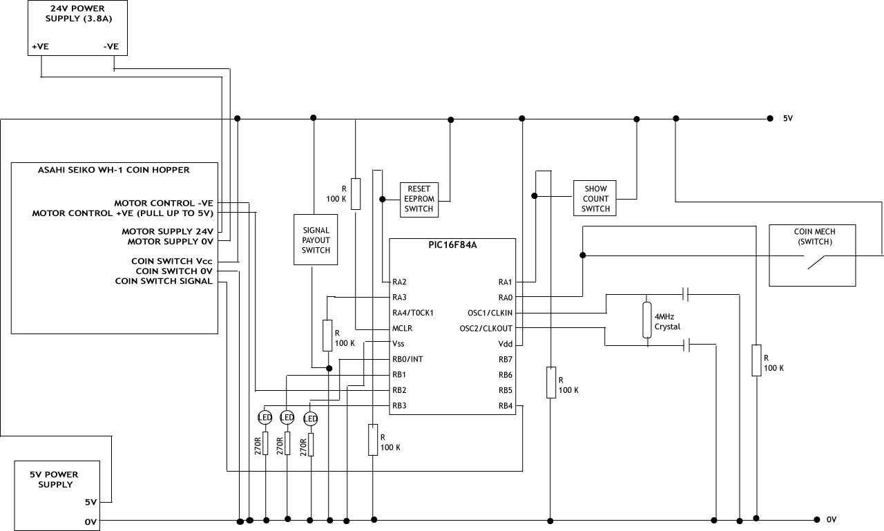
This is what it does:

- PIC16F84A manages the count of coins inside the machine
- Coin mech switch triggers the increment count function
- Inside the PIC the count is maintained in EEPROM and volatile RAM, this is because it's easier to manipulate data in the RAM and then update the EEPROM.
- The increment function increments the RAM count then updates the count in the EEPROM to equal the RAM count.
- PIC16F84A have 8 bit registers which means that one register can only count up to 256, since we need to be able to count up to 800 (the amount the hopper holds) we need to use 2 registers, these are COUNT1 and COUNT2. The starting values for 0 coins should be 0 in COUNT1 and 1 in COUNT2. The reason for this is when we are decrementing the count using DECFSZ the program flow will branch depending if the result of the decrement is 0 or not 0. We can assume COUNT1 will always be at least one when it comes time to spit out the coins because the player could not have got to the end of the game without putting in any money, however COUNT2 must start at 1 so when the COUNT2 decrement occurs (ie after COUNT1 reaches 0) we get a 0 instead of a 255.
- The switch connected to RA1 is used to query the number of coins in the machine, this is only used for testing and i haven't implemented logic to deal with counts over 256. When the switch is pressed the LED on RB0 will flash a number of times equal to the number of coins in the machine.
- The switch on RA2 resets the EEPROM (and the local count) by setting the local COUNT1 AND COUNT2 to 0 and 1 respectively and copying those values to EEPROM.
- The switch on RA3 initiates a payout, i still have to implement some kind of serial or parallel communication with the PC and MAME, currently its just a push button switch.
- The LED connected to RB1 lights up when the EEPROM is being written
- The LED connected to RB3 lights up when a coin is dispensed
- RB2 controls the hoppers motor, 5v for on, 0v for off

Here is a picture of the circuit diagram:


Here is my source code for the PIC so far also, I can't really be bothered going over it right now, might do a better description later, right now i want to figure out the PC - PIC communication
;**************************************************************************
;*                               COIN COUNTER                              *
;**************************************************************************
;*          (C) DIRK & DIRK,2009  All rights reserved                       *
;*          Hardware & software by Dirk                                        *
;**************************************************************************
;*          Hardw. Rev: 1                 Softw. Rev:  1.01                *
;*          OSC.......: XT 4MHz Max.     POWER.....:  5V DC              *
;**************************************************************************
;==========================================================================
;    Counts coins:
;        - Each coin triggers an update to the EEPROM
;        - Count is maintained in EEBYTE1 & EEBYTE2 and volatile
;          variables COUNT1 & COUNT2
;        - LED connected to RB0 flashes x times; where x is the coin
;          count
;        - NOTE: Querying the count when it's 0 or over 256 will produce
;          odd effects
;        - LED connected to RB1 is on when EEPROM is being written
;        - RA0: Increment count
;        - RA1: Query value of coin count
;        - RA2: Reset EEPROM
;==========================================================================

;==========================================================================
;
;       Configuration Bits
;
;==========================================================================
_CP_ON                       EQU     H'000F'
_CP_OFF                      EQU     H'3FFF'
_PWRTE_ON                    EQU     H'3FF7'
_PWRTE_OFF                   EQU     H'3FFF'
_WDT_ON                      EQU     H'3FFF'
_WDT_OFF                     EQU     H'3FFB'
_LP_OSC                      EQU     H'3FFC'
_XT_OSC                      EQU     H'3FFD'
_HS_OSC                      EQU     H'3FFE'
_RC_OSC                      EQU     H'3FFF'
    __CONFIG        _CP_OFF & _PWRTE_ON & _WDT_OFF & _XT_OSC

;==========================================================================
;
;       Register Definitions
;
;==========================================================================
W                            EQU     H'0000'
F                            EQU     H'0001'
;----- Register Files------------------------------------------------------
INDF                         EQU     H'0000'
TMR0                         EQU     H'0001'
PCL                          EQU     H'0002'
STATUS                       EQU     H'0003'
FSR                          EQU     H'0004'
PORTA                        EQU     H'0005'
PORTB                        EQU     H'0006'
EEDATA                       EQU     H'0008'
EEADR                        EQU     H'0009'
PCLATH                       EQU     H'000A'
INTCON                       EQU     H'000B'
OPTION_REG                   EQU     H'0081'
TRISA                        EQU     H'0085'
TRISB                        EQU     H'0086'
EECON1                       EQU     H'0088'
EECON2                       EQU     H'0089'
;----- STATUS Bits --------------------------------------------------------
IRP                          EQU     H'0007'
RP1                          EQU     H'0006'
RP0                          EQU     H'0005'
NOT_TO                       EQU     H'0004'
NOT_PD                       EQU     H'0003'
Z                            EQU     H'0002'
DC                           EQU     H'0001'
C                            EQU     H'0000'
;----- INTCON Bits --------------------------------------------------------
GIE                          EQU     H'0007'
EEIE                         EQU     H'0006'
T0IE                         EQU     H'0005'
INTE                         EQU     H'0004'
RBIE                         EQU     H'0003'
T0IF                         EQU     H'0002'
INTF                         EQU     H'0001'
RBIF                         EQU     H'0000'
;----- OPTION_REG Bits ----------------------------------------------------
NOT_RBPU                     EQU     H'0007'
INTEDG                       EQU     H'0006'
T0CS                         EQU     H'0005'
T0SE                         EQU     H'0004'
PSA                          EQU     H'0003'
PS2                          EQU     H'0002'
PS1                          EQU     H'0001'
PS0                          EQU     H'0000'
;----- EECON1 Bits --------------------------------------------------------
EEIF                         EQU     H'0004'
WRERR                        EQU     H'0003'
WREN                         EQU     H'0002'
WR                           EQU     H'0001'
RD                           EQU     H'0000'
;INPUTS
SW1        EQU     H'00'        ;SW1 is triggering RA0 (Increment)
SW2        EQU     H'01'        ;SW2 is triggering RA1 (Flash value of count times on RB0)
SW3        EQU        H'02'        ;SW3 is triggering RA2 (Reset EEPROM)
SW4        EQU        H'03'        ;SW4 is triggering RA3 (Signal payout)
SW5        EQU        H'04'        ;SW5 is triggering RB4 (decrement coin signal)
;OUTPUTS
PO        EQU        H'02'        ;PO is triggering RA4 (switch on coin hopper motor)
;==========================================================================
;
;       RAM Definition
;
;==========================================================================
        __MAXRAM H'CF'
        __BADRAM H'07', H'50'-H'7F', H'87'

;==========================================================================
;
;       Variables
;
;==========================================================================
COUNT1            EQU        H'0C'    ;Local count byte 1
COUNT2            EQU        H'0D'    ;Local count byte 2
DECRM            EQU        H'0E'    ;Stores temp value of count for flashing
TIMER1          EQU     H'0F'   ;Timer 1, Used for general delay
TIMER2          EQU     H'10'   ;Timer 2, used for delay !
FREQCOUNT        EQU        H'11'    ;Frequency counter
;==========================================================================
;
;       EEPROM Variables
;
;==========================================================================
EEBYTE1            EQU        H'00'    ;Stores the first byte of the count in the eeprom
EEBYTE2            EQU        H'01'    ;Stores the second byte of the count in the eeprom

        ORG        0                ;Setting Reset vector, reset vector address is 000h in PIC16F84
        GOTO    RESET            ;Jump to RESET procedure when boot-up PIC device.


;**************************
;*     main routine:      *
;**************************
RESET    BSF        STATUS,RP0        ;Jump to bank 1 of PIC16F84 to access special registers.
        MOVLW    B'00001111'        ;Config Port A, Low nibble = Ra0 are inputs, high nibble not implemented.
        MOVWF    TRISA            ;Set I/O configuration for PORTA
        MOVLW    B'00010000'        ;Rb7...Rb0 are outputs.
        MOVWF    TRISB            ;Set I/O configuration for PORTB
        BCF    STATUS,RP0            ;Jump back to bank 0 of PIC.
        CLRF    PORTA            ;Clear all I/O's of PORTA
        CLRF    PORTB            ;Clear all I/O's of PORTB
        CALL    FETCHEEPROM
                                ;Loop starts here !!!
LOOP    BTFSC     PORTA,SW1        ;See if button 1 is on (increment button)
        CALL    INCREM            ;Increment the count
        BTFSC    PORTA,SW2        ;See if button 2 is down (flash the number of the count)
        CALL    SHOWCOUNT        ;Start flasher
        BTFSC    PORTA,SW3        ;See if button 3 is on (reset eeprom)
        CALL    RESETEEPROM        ;Reset eeprom
        BTFSC    PORTA,SW4        ;See if button 4 is on (payout signal)
        CALL    PAYOUT            ;Begin payout function
        GOTO     LOOP
;*******************
;* Payout function *
;*******************
PAYOUT    CALL    PAYON            ;Switch hopper motor on
        CALL    DELAY
; Probably not the right way to do it but this part checks the switch 5 times to make
; sure it isn't that weird spiking thing.
P1        BTFSS    PORTB,4            ;Is the coin decrement switch on?
        GOTO    P1                ;No
        BTFSS    PORTB,4            ;Is the coin decrement switch on?
        GOTO    P1                ;No
        BTFSS    PORTB,4            ;Is the coin decrement switch on?
        GOTO    P1                ;No
        BTFSS    PORTB,4            ;Is the coin decrement switch on?
        GOTO    P1                ;No
        BTFSS    PORTB,4            ;Is the coin decrement switch on?
        GOTO    P1                ;No
        BSF        PORTB,3            ;Real decr switch occurred, switch light on
P2        BTFSC    PORTB,4            ;Is the coin decrement switch up?
        GOTO    P2                ;No
        BCF        PORTB,3            ;End of decr switch, turn off light
DEC1    DECFSZ    COUNT1,1        ;Decrement first count byte
        GOTO    P1                ;COUNT1 != 0, so go back to P1
        DECFSZ    COUNT2,1        ;COUNT1 == 0, now check COUNT2
        GOTO    DEC2            ;COUNT2    != 0, so set COUNT1 = D'255' then go back to P1
        GOTO    DEC3            ;COUNT2 == 0, hopper is empty, go to DEC3 to halt and clean up
DEC2    MOVLW    H'FF'            ;
        MOVWF    COUNT1            ;Set count back to FF (256)
        GOTO     P1                ;Start checking for clicks again
DEC3    CALL    PAYOFF            ;Switch of the motor
        CALL     RESETEEPROM        ;Reset count to 0 (count1:0, count2:1)
        RETURN

;        BCF        PORTB,3            ;FOO: This is just to check if a switch signal is received from the hopper
;P2        BTFSC    PORTB,SW5        ;Is the coin dec switch off?
;        GOTO    P2                ;No, go back
; Here one switch from the hopper has occurred, now decrement count
; and check to see if we are at 0
;DEC1    DECFSZ    COUNT1,1        ;Decrement first count byte
;        GOTO    P1                ;COUNT1 != 0, so go back to P1
;        DECFSZ    COUNT2,1        ;COUNT1 == 0, now check COUNT2
;        GOTO    DEC2            ;COUNT2    != 0, so set COUNT1 = D'255' then go back to P1
;        GOTO    DEC3            ;COUNT2 == 0, hopper is empty, go to DEC3 to halt and clean up
;DEC2    MOVLW    H'FF'            ;
;        MOVWF    COUNT1            ;Set count back to FF (256)
;        GOTO     P1                ;Start checking for clicks again
;DEC3    CALL    PAYOFF            ;Switch of the motor
;        CALL     RESETEEPROM        ;Reset count to 0 (count1:0, count2:1)
;        RETURN
;TEMPTEMPTEMPTEMPTEMPTEMPTEMPTEMP
;LED4ON    MOVLW    H'01'
;        MOVWF    FREQCOUNT
;ITSON    BTFSS    PORTB,SW5
;        GOTO    STILLON
;        GOTO     GONEOFF
;STILLON    DECFSZ    FREQCOUNT,1
;        GOTO    ITSON
;LOOPER    BSF        PORTB,3
;        GOTO    LOOPER
;GONEOFF    GOTO    P1
;LED4OFF    BCF        PORTB,3
;        GOTO    P1

;PAYOUT    BTFSC    PORTA,SW4        ;Is button down?
;        GOTO    PAYON            ;Yes
;        GOTO    PAYOFF            ;No
;**********************
;* Payout on function *
;**********************
PAYON    BSF        PORTB,PO        ;Set PO pin to high
        RETURN
;***********************
;* Payout off function *
;***********************
PAYOFF    BCF        PORTB,PO        ;Set PO pin to low
        RETURN                    ;
;******************************
;* Count incrementer function *
;******************************
INCREM    BTFSC    PORTA,SW1        ;Make sure they aren't still holding down the button
        GOTO    INCREM            ;
        CALL    DELAY            ;Short delay for mechanical bouncing on the button
        INCFSZ    COUNT1,1        ;Increment COUNT1 register
        GOTO    WRTRET            ;Go to write then return section if COUNT1 didn't click over to 0
        INCFSZ    COUNT2,1        ;Increment COUNT2 register if COUNT1 did click over to 0
WRTRET    CALL     SETEEPROM        ;
        RETURN                    ;
;********************
;* Flasher function *
;********************
;##############################################################################################################
;################ FOO: NEEDS TO BE UPDATED FOR 2 BYTE COUNT ###################################################
;##############################################################################################################
SHOWCOUNT    BTFSC    PORTA,SW2    ;Make sure they aren't still holding down the button
            GOTO    SHOWCOUNT    ;
            MOVF    COUNT1,0    ;Move the count to W
            MOVWF    DECRM        ;Move W to decrm register
MORECOUNT    CALL    LED1ON        ;Switch LED on
            CALL    DELAY        ;Wait
            CALL    LED1OFF        ;Switch LED off
            CALL    DELAY        ;Wait
            DECFSZ    DECRM,1        ;Decrement count
            GOTO     MORECOUNT
            RETURN
;*******************************************************
;* Fetches count from EEPROM, moves to COUNT1 & COUNT2 *
;*******************************************************
FETCHEEPROM    MOVLW    EEBYTE1            ;Grab first byte
            MOVWF    EEADR            ;Address to read
            BSF        STATUS,RP0        ;Bank 1
            BSF        EECON1,RD        ;EE read
            BCF        STATUS,RP0        ;Bank 0
            MOVF    EEDATA,0        ;Copy EEDATA to W
            MOVWF    COUNT1            ;Copy EEDATA (from W) to COUNT1
            MOVLW    EEBYTE2            ;Grab second byte
            MOVWF    EEADR            ;Address to read
            BSF        STATUS,RP0        ;Bank 1
            BSF        EECON1,RD        ;EE read
            BCF        STATUS,RP0        ;Bank 0
            MOVF    EEDATA,0        ;Copy EEDATA to W
            MOVWF    COUNT2            ;Copy EEDATA (from W) to COUNT2
            RETURN
;******************************
;* Reset EEPROM function      *
;* - Sets COUNT1 & COUNT2 to  *
;      0 then writes the EEPROM *
;******************************
RESETEEPROM    MOVLW    H'0'        ;Move 0 into W
            MOVWF    COUNT1        ;Move W into COUNT1
            MOVLW    H'1'        ;Move 0 into W
            MOVWF    COUNT2        ;Move 0 into COUNT2
            CALL     SETEEPROM    ;Now set EEPROM since COUNT1 & COUNT2 are 0
            RETURN                ;Return from reset call
;**************************************
;* Set EEPROM function                *
;* - Writes COUNT1 & COUNT2 to EEPROM *
;**************************************
; Write the first byte
SETEEPROM    CALL    LED2ON        ;Turn on LED 2 to show it's writing
            BCF        STATUS,RP0    ;Bank 0
            MOVF    COUNT1,0    ;Move COUNT1 into EEDATA for writing
            MOVWF    EEDATA
            MOVLW    EEBYTE1        ;Address to read from (EEBYTE1)
            MOVWF    EEADR
            BSF        STATUS,RP0    ;Bank 1
            BCF        INTCON,GIE    ;Disable interrupts
            BSF        EECON1,WREN    ;Enable write
            MOVLW    H'55'        ;Confirm write 1
            MOVWF    EECON2        ;
            MOVLW    H'AA'        ;Confirm write 2
            MOVWF    EECON2        ;
            BSF        EECON1,WR    ;Set WR bit, begin write
            BSF     INTCON,GIE    ;Enable INT's
            CALL     WAITFOREE    ;Wait for EE to be written
; Write the second byte
            BCF        STATUS,RP0    ;Bank 0
            MOVF    COUNT2,0    ;Move COUNT2 into EEDATA for writing
            MOVWF    EEDATA
            MOVLW    EEBYTE2        ;Address to read from (EEBYTE2)
            MOVWF    EEADR
            BSF        STATUS,RP0    ;Bank 1
            BCF        INTCON,GIE    ;Disable interrupts
            BSF        EECON1,WREN    ;Enable write
            MOVLW    H'55'        ;Confirm write 1
            MOVWF    EECON2        ;
            MOVLW    H'AA'        ;Confirm write 2
            MOVWF    EECON2        ;
            BSF        EECON1,WR    ;Set WR bit, begin write
            BSF        INTCON,GIE    ;Enable INT's
            CALL    WAITFOREE    ;Wait for EE to be written
            BCF        STATUS,RP0    ;Bank 0
            CALL    LED2OFF        ;Switch off LED to show stopped writing
            RETURN                ;End of reset EEPROM function
;**********************************
;* Waits for EEPROM to be written *
;**********************************
WAITFOREE    BTFSC    EECON1,WR    ;Check if WR is still 1
            GOTO    WAITFOREE    ;Yes, go back
            RETURN                ;No return
;*******************
;* LED 1 on function *
;*******************
LED1ON    BSF        PORTB,0
        RETURN

;********************
;* LED 1 off function *
;*********************
LED1OFF    BCF        PORTB,0
        RETURN
;*********************
;* LED 2 on function *
;*********************
LED2ON    BSF        PORTB,1
        RETURN
;**********************
;* LED 2 off function *
;**********************
LED2OFF    BCF        PORTB,1
        RETURN
;******************
;* Delay function *
;******************
DELAY    MOVLW   D'250'          ;*    ;Put 150 decimal in the 'TIMER1' register.
           MOVWF   TIMER1          ;*
                                   ;
DELAY2    MOVLW    D'250'            ;Put 150 decimal in the 'TIMER2' register.
        MOVWF    TIMER2
        DECFSZ  TIMER2,F        ;*    ;Timer2 = Timer2 -1, skip next instruction if Timer2 = 0.
                GOTO    $-1     ;*    ;Jump back 1 instruction.

        DECFSZ    TIMER1,F        ;Timer1 = Timer1 - 1, skip next instruction if Timer1 = 0
        GOTO    DELAY2            ;Jump to 'DELAY2' routine
        RETLW   0                ;Return (jump back to main) and load W-reg with 0.
        END                     ;End of source code.
Progress

2009-02-08 14:38:02

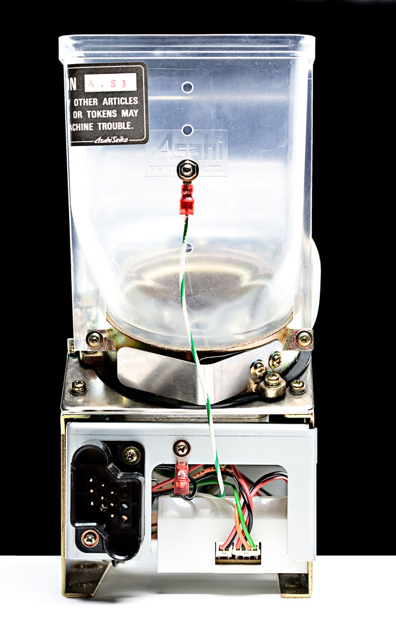
Still no cabinet but I'm starting to understand the coin hopper and I've been boning up on my electronics type skills. Heres a picture of the coin hopper in all its greatness. (Nice photo huh? Shmoz took it!)


Coins go in the top and get spat out the other side. Since it didn't come with a manual I got in contact with the manufacturers and they kindy sent me the manual.

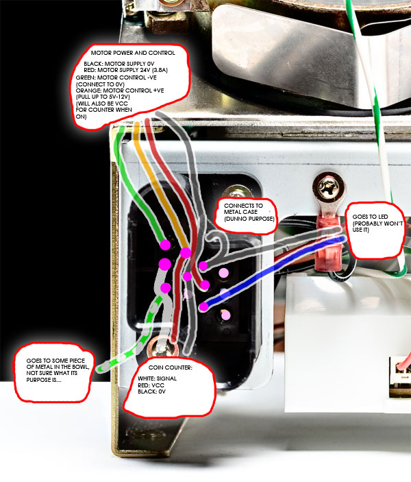
Heres a picture of the external connector with what the wires behind it are:


The pin numbers are from top left to bottom left 1,2,3 then top 2nd left to bottom 2nd left 4,5,6 and so on for the 12 pins. Pins 6,10,11, and 12 aren't connected. I probably won't use pins 7 and 9 because i don't really know what to do with them, and I'm not sure was pin 3 is for but if i had to guess i'd say its meant to be connected to ground.

Interestingly (to me at least because i never look at circuit boards) pin 4 will get 5-12 volts when its time to tell the hopper to pay out, the orange wire connected to this pin activates the motor when its >5v and the red wire will power the vcc of the coin counter switch, its like 2 in one!

So now that i have that all figured out (sort of) i can think about how im going to make the control circuit to interface between the PC and the hopper and the coin mech. I'm going to need to use a chip with eeprom (memory thats data after the chip is powered down) to hold the number of coins in the bowl, this number must stop at about 800 because once it reaches that amount of coins i am expecting them to spill out of the bowl down into my 100% profit catcher! I don't want people to think they're going to win $1300 when the hopper will only spit out $800. The switch connected to the coin mech will increment the total amount and the switch from the hopper will decrement that count. Obvious when decrementing the number the power on the control circuit should switch off once the count reaches 0.

I have a bunch of pic18f2455's with eeprom but they're surface mount which i can't test on my bread board without waiting for parts, i've got a bunch of pic16f84a's with eeprom but no native USB, probably not a problem and ill probably use these.

I'm also going to need a 24 DC power suppy that can output 3.8V, which from looking in my altronics catalogue, is going to be pretty expensive, but i don't really know what my options are as far as power for the hopper goes so ill ask the lords at altronics and report back.

I need to get a USB to RS232 (serial) converter for my PIC programmer so i can flash my chips.

I need a leaf switch for the coins to bounce off before they fall into the coin bowl on the hopper.

Still need to get a cabinet.

2009-02-04 06:41:08

No coin hopper, no cabinet, fuking rats!

To-day!

2009-02-03 22:19:03

The cabinet dude reckons he'll have the cabinet ready for me in his warehouse, Jack is laying 5-1 odds that he'll call me, I think those odds are pretty fair. Also the hopper should be arriving some time today also which will mean I will finally have all the parts I need, but it's annoying because the wait has made me lose a bit of enthusiam and get psched on another project (as usual), I'm not letting that stop me though, as soon as I get everything I'm committing until it's done. Actually, just writing this post is making me froth, alright the enthusiasm is back!!

2009-01-31 02:10:31

They didn't call... rats

2009-01-29 21:07:17

... he's going to get back to me later today...!

Cabinet

2009-01-29 21:02:04

Is this guy I'm trying to buy the cabinet off avoiding me?

A few days ago I call and he says he'll get back to me in 24 hours... nothing, yesterday i call him, he tells me hes on the other line and that he'll call me back... nothing. I hope he isn't one of those arcade purist jerks that never wants people to "desicrate" original arcade machines by turning them into mame machines, like those low boys were ever something special. I could make one up myself pretty easily if I didn't suck at woodwork. Oh well, I'll try him again today.

Getting a cabinet

2009-01-28 02:13:10

That orbit place is pretty much gone, downstairs is now a shop that sells bongs and weed paraphenalia, and upstairs is all the arcade machines, not a single person in there and no attendants, it would be packed if it was filled with hacked versions that gave you the abilty to win all the money in the machine! Probably not that profitable tho. But anyway they don't have any of their old cabinets there any more so I called some places called Omnicoin and the dude tells me they have heaps of 20" Australian Low Boys for $200 for an empty cabinet, and is gunna call me in the next 24 hours to let me know which of their warehouses to go to to get it. Its one of these types:


..generic australian low boy style, which is exactly what i want. I'm thinking about having an LCD display in the top bit where the marquee goes that shows how much $$ is in the machine.

Building the machine

2009-01-28 00:48:53

Going to scope out some cabinets at an arcade in the city today, I've noticed a bunch of empty old ones at this place in a back room, and they've got a sign out the front saying "arcade machines for sale" so I'll see how I'll go.

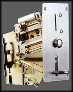
Got my coin mech set up to accept $1 coins, its this one:


And I got it from OzSitck, but I bought it a few years ago before there were any other places to buy these in Australia. I wouldn't really recommend buying from there, they were easy to deal with and delivered fast, but the mech came with the wrong microswitch and no instructions and confused the shit out of me for a long time. Once the coins fall out the mech (bottom left of above picture) you've left to deal with the registering of the coin, so the switch I'll need to get will look something like this:


...so the coin can bounce off the switch into the hopper, the switch that came with it was a regular push button switch which wasn't much use in this application.

I'm attempting to buy this hopper:


..from highway entertainment but they're a bit slow to respond to order. Unfortunately the only other place in Australia I've found to buy coin hoppers is JEA Technologies but they seem extremely unorganized or uninterested in dealing with retail, its a shame because they stock a hopper that looks a bit better than the one from highway, the himecs 85a, but fuck it, I'd rather get it done then if this doesn't perform I'll change it later.

Right, going to scope these cabinets now.

Raiden hacking: Done!

2009-01-27 05:21:43

Now all i have to do is get a coin hopper and make mame tell the hopper to dump at a certain time.

Inside the cpu emulator nec.c the function static CPU_EXECUTE( necv ) i have an if statement:

if (((nec_state->sregs[PS]<<4) + nec_state->ip) == 0xF1E67)

which checks to see if the instruction being executed is the one i found at the end of the game (F1E67), then inside there i just put my code to talk to the hopper!

2009-01-27 04:55:26

Yep it is...

I am the fucking MAN!

2009-01-27 04:07:47

OH SHIT!!! i think i might have just found the instruction

F1E67 on the main chip!!!

pretty much frothing right now, just gotta play the whole game through to check it isn't called anywhere else, its looking promising tho!

Making Progress

2009-01-25 03:55:48

OK figured out that since I need to be monitoring the value of the Program Counter (PC) which is a register on the CPU of the game that I needed to look in CPU emulator files. Raiden uses an NEC chip for most stuff and z80 for the sound. Don't really need to worry about sound so scoping out the nec.c & nec.h files.

This is what the nec.c calls to send the value of the PC to the debugger.

debugger_instruction_hook(device, (nec_state->sregs[PS]<<4) + nec_state->ip);

Nasty! So I guess this "(nec_state->sregs[PS]<<4) + nec_state->ip" is what I need to monitor, but what the heck is that <<, is that some inline shit that changes the value of sreqs?? My poor brain!

Actually I've gotta say the code in MAME is pretty much impeccible and there are a lot of helpful comments, much neater than anything I've ever written.

Right so now I've gotta start slowly stepping through Raiden looking for code that exectues at the end of the game. I know the best way to do it is to look in memory for plain text stuff like "Congradulations, you finished Raiden" then find the intruction that calls that memory but how the shit do I do that? The program window of the debugger doesn't give you the whole range of the CPU, or at least I don't think it does, I can't search for it, are these logical or relative or physical addresses? I can't even remember how a freakn CPU works, too much time written OO code.

TODO:
- Figure out how I'm going to send a signal from mame when the game is completed to the coin hopper.
- Find a cabinet at a Timezone or whatever so I don't have build my own.

First post!

2009-01-17 03:59:50

Where I'm at:

Finally compiled mame on my vista64 machine with the special mingw version from http://mamedev.org/tools/ and following the instructions on that page. Had lots of troubles because i still had DJGPP in my path variable, which meant the makefile was running from mingw but somehow compiling with djgpp? anyway, got rid of djgpp and all the occurances of it in the path and env variables and it compiled fine.

Now i gotta figure out how to change mame to intercept when certain address locations are accessed in the raiden rom so i can send a signal to the coin hopper, fuck knows how I'm going to that, its gunna take a lot of reading and brushing up of my C skills which at the moment are pretty average!